This simulation uses the Rigid Body Physics Engine to show objects moving in 2 dimensions with various forces applied.
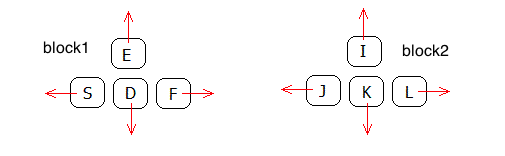
Click near an object to exert a spring force with your mouse. With the keyboard you can control four "thrusters". The keys S,D,F,E control thrust on block1. The keys J,K,L,I (and also the arrow keys) control thrust on block2. You can also set gravity and damping (friction). You can choose from one to six objects. The mass of the green object is adjustable (the others are set to mass 1.0).
Also available: source code, documentation and how to customize.
If you play around with the simulation shown above, you will notice that it can easily get "stuck", which means that objects wind up overlapping. The section below about Resting Contact explains why this happens.
Here is a picture of how the keyboard controls are arranged. If the keys don't work, try clicking near an object first - this ensures that keystrokes are passed to the simulation.
Click the "show energy" checkbox to see the bar graph showing the potential, rotational and translational energy.
See the section on Energy and Momentum for how these quantities are calculated.
Ignoring collisions for the moment, we develop the equations of motion for the objects. The forces on the objects are
For each body, there are three variables to specify position:
In addition, each body has a velocity corresponding to each of these positions:
The equations of motion for the body involve the total force F = (Fx, Fy) and torque τ on the body as follows:
Fx = m x''
Fy = m y''
τ = I θ''
where m = mass and I = moment of inertia about the center of mass (moment of inertia is defined in the next section). Note that we indicate vectors, such as F , with bold and an overline.
We now build up the equations of motion by adding in one force at a time, beginning with the thrust force. Let T = (Tx, Ty) be the thrust force vector which operates at the point P on the body. The thrust force will accelerate the body according to
m x'' = Tx
m y'' = Ty
In these equations it doesn't matter where on the body the thrust force is applied. The point P can be anywhere on the body, yet because the body is rigid the thrust accelerates the entire body. On the other hand, for rotational movement it matters a great deal where on the body the thrust is applied.
Moment of inertia is the equivalent of mass for rotational physics. It measures how difficult it is to rotate a body about a given point. Since our rectangle bodies rotate freely about their center of mass, we use center of mass as the point for calculating moment of inertia. From a physics textbook you can find the equation for the moment of inertia about the center of a thin rectangular plate. It is given by
I = m (width2 + height2) ⁄ 12
Let R = (Rx, Ry) = be the distance vector from center of mass to P . The torque at the point P is given by the vector cross product
R × T = Rx Ty − Ry Tx
so we have
I θ'' = R × T
Actually torque is a vector, but since we are working in 2 dimensions we know that torque is always perpendicular to the plane and so we aren't using vector notation for it. The true vector cross product results in a vector. So the above cross product corresponds to the following 3 dimensional calculation:
(Rx, Ry, 0) × (Tx, Ty, 0) = (0, 0, Rx Ty − Ry Tx)
You can see that the result is always perpendicular to the plane, with zero x and y components. The general vector cross product of two vectors is defined as:
(x, y, z) × (u, v, w) = (y w − z v, −x w + z u, x v − y u)
The spring force in the simulation operates along the vector from point P on the body to the mouse position, call this vector L . The spring force is B = (Bx, By) = s L where s is the stretchiness constant. The treatment of this force is identical to the thrust force, so we add it in to get the following equations.
m x'' = Tx + Bx
m y'' = Ty + By
I θ'' = R×T + R×B
Let g = the gravitational constant. Gravity causes a force on the center of mass of −m g in the vertical direction leading to
m y'' = Ty + By − m g
Because gravity works on all points of the body, no torque is generated by gravity.
Damping (friction) causes a force opposite to the direction of motion. The faster you go, the more friction resists your motion. So the magnitude of the damping force is proportional to the velocity. Let k = the proportional damping constant. Adding this to our equations of motion gives
| m x'' = Tx + Bx − k x' | (1) |
| m y'' = Ty + By − m g − k y' | (2) |
| I θ'' = R×T + R×B − k θ' | (3) |
In a more realistic simulation, there may be different damping constants for rotational versus translational motion. But here, we use the same constant for both.
Equations (1-3) are the equations of motion for one of our rectangular bodies. As long as no collision occurs, these equations are in charge. Here is a recap of some of the variables:
The above section shows the equations of motion for bodies affected by gravity, damping, a thrust force and a spring force. To use the Runge Kutta method for solving a set of differential equations we need to convert the above three second order equations into six first order equations. Define the velocity variables
Then equations (1-3) become 6 first order differential equations
x' = vx
y' = vy
θ' = ω
vx' = (Tx + Bx − k vx) ⁄ m
vy' = (Ty + By − m g − k vy) ⁄ m
ω' = (R × T + R × B − k ω) ⁄ I
These equations are now in the form needed for solving numerically with the Runge-Kutta method. Each rectangle body will have its own set of 6 variables (3 positions x, y, θ and 3 velocities vx, vy, ω ) and 6 first order differential equations.
This section explains how the energy and momentum of the objects are calculated. See the description of the energy bar graph for how to observe these quantities in the simulation.
If there is no loss of energy to friction (damping = 0 ) or during collisions (elasticity = 1 ) then the energy of the system should not change.
A collision between objects should not change the angular momentum. However, a collision with a wall will not preserve angular momentum because the super massive walls are not included in the calculations of the momentum of the objects.
Gravitational energy is given by m g h where h = height of the object's center of mass above the floor.
Translational energy is 1⁄2 m v2 where v is the velocity vector for the object's center of mass. Note that we use vector dot product to square the velocity vector.
Rotational energy is 1/2 I ω2 where I is the moment of inertia and ω is the angular velocity.
Linear momentum in the horizontal direction is given by m vx , in the vertical direction by m vy .
Angular momentum is measured with regard to a particular point in space, for example the origin. It is given by:
I ω k + m r × v
where r is the distance vector from the origin to the object's center of mass. The vector k is the unit z vector, which points out of the x-y plane. You can see that the angular momentum has two components: the spinning component I ω k and the rotation about the origin given by the vector cross-product m r × v .
This web page was first published February 2003.